We’ve all been there: staring at a breadboard buried under a rat’s nest of jumper wires, trying to figure out why your standalone display isn’t communicating with your microcontroller. When I set out to build an RFID reader, I knew I wanted a clean, functional user interface without the usual hardware spaghetti. Enter the ESP32-CYD (Cheap Yellow Display). It will allow a user to scan an RFID tag and show the information on the CYD.
In this post, I’ll walk you through how to build a fully functional RFID reader using the CYD. We’ll cover the hardware connections, the software setup, and how to get a clean UI up and running. If you haven’t worked with the CYD yet, it’s about to become your go-to board for interactive projects. Here’s why it’s the perfect fit for this build:
- All-in-One Integration: It combines a dual-core ESP32, a 2.8-inch TFT display, and a resistive touch screen on a single, affordable board. No more wiring displays from scratch.
- Built-in Connectivity: Thanks to the ESP32 backbone, logging RFID scans to a local server or home network over Wi-Fi is practically native.
- Accessible I/O: Despite the integrated screen, the CYD still exposes the necessary pins (like the SPI bus) to easily interface with common RFID modules like the RC522 or PN532.
Bill of Materials (BOM)
- Display/MCU: ESP32-2432S028R (The standard 2.8″ CYD with ILI9341 display and resistive touch)
- RFID Module: MFRC522 Reader (13.56 MHz)
- RFID Tags: Mifare Classic 1K Cards or Keyfobs (usually included with the MFRC522)
- Wiring: 7x Dupont jumper wires (female-to-female or soldered directly)
- Power: Micro-USB or USB-C cable (depending on your specific CYD variant)
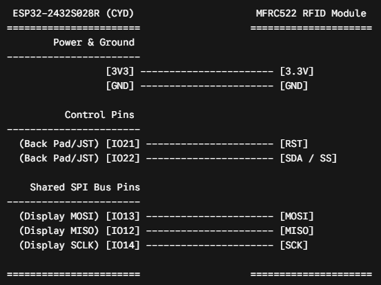
Wiring Guide (Shared SPI Bus)
| MFRC522 Pin | ESP32-2432S028R Pin | Function |
| 3.3V | 3V3 | Power (Do not use 5V) |
| RST | IO21 | Reset (Available on back JST/pads) |
| GND | GND | Ground |
| MISO | IO12 | Shared SPI Data Out |
| MOSI | IO13 | Shared SPI Data In |
| SCK | IO14 | Shared SPI Clock |
| SDA (SS) | IO22 | Chip Select (Available on back JST/pads) |
PlatformIO Configuration
Instead of modifying the TFT_eSPI library files manually, you can inject the hardware configuration directly into your platformio.ini file. This makes the project highly portable.
platform.ini
[env:esp32dev]
platform = espressif32
board = esp32dev
framework = arduino
monitor_speed = 115200
lib_deps =
bodmer/TFT_eSPI @ ^2.5.31
miguelbalboa/MFRC522 @ ^1.0.10
build_flags =
-D USER_SETUP_LOADED=1
-D ILI9341_2_DRIVER=1
-D TFT_WIDTH=240
-D TFT_HEIGHT=320
-D TFT_MISO=12
-D TFT_MOSI=13
-D TFT_SCLK=14
-D TFT_CS=15
-D TFT_DC=2
-D TFT_RST=-1
-D TFT_BL=21
-D TFT_BACKLIGHT_ON=HIGH
-D LOAD_GLCD=1
-D LOAD_FONT2=1
-D LOAD_FONT4=1
-D SPI_FREQUENCY=27000000
Application Code
This code initializes the shared SPI bus, waits for an RFID tag to be presented, and prints the Unique ID (UID) of the tag to the center of the display.
main.cpp
#include <Arduino.h>
#include <SPI.h>
#include <TFT_eSPI.h>
#include <MFRC522.h>

// RFID Pins
#define RST_PIN 21
#define SS_PIN  22

// Initialize display and RFID instances
TFT_eSPI tft = TFT_eSPI();
MFRC522 mfrc522(SS_PIN, RST_PIN);

void setup() {
  Serial.begin(115200);

  // Initialize the TFT Display
  tft.init();
  tft.setRotation(1); // Landscape mode
  tft.fillScreen(TFT_BLACK);

  // Draw static UI elements (Dark Mode Aesthetic)
  tft.setTextColor(TFT_CYAN, TFT_BLACK);
  tft.setTextDatum(MC_DATUM); // Set text alignment to middle-center
  tft.drawString("RFID Scanner Ready", tft.width() / 2, 40, 4);
  tft.drawLine(20, 60, tft.width() - 20, 60, TFT_DARKGREY);

  tft.setTextColor(TFT_WHITE, TFT_BLACK);
  tft.drawString("Please scan a tag...", tft.width() / 2, tft.height() / 2, 2);

  // Initialize SPI bus and MFRC522
  SPI.begin();
  mfrc522.PCD_Init();

  Serial.println(F("System initialized. Waiting for RFID tags..."));
}

void loop() {
  // Look for new cards
  if (!mfrc522.PICC_IsNewCardPresent()) {
    return;
  }

  // Select one of the cards
  if (!mfrc522.PICC_ReadCardSerial()) {
    return;
  }

  // Clear the middle area of the screen for the new ID
  tft.fillRect(0, 100, tft.width(), 100, TFT_BLACK);

  // Build the UID string
  String uidString = "";
  for (byte i = 0; i < mfrc522.uid.size; i++) {
    if (mfrc522.uid.uidByte[i] < 0x10) {
      uidString += "0";
    }
    uidString += String(mfrc522.uid.uidByte[i], HEX);
    if (i < mfrc522.uid.size - 1) {
      uidString += ":";
    }
  }

  uidString.toUpperCase();

  // Print to Serial
  Serial.print(F("Card UID: "));
  Serial.println(uidString);

  // Update TFT Display
  tft.setTextColor(TFT_GREEN, TFT_BLACK);
  tft.drawString("Tag Detected!", tft.width() / 2, 120, 2);

  tft.setTextColor(TFT_YELLOW, TFT_BLACK);
  tft.drawString(uidString, tft.width() / 2, 160, 4);

  // Halt PICC to prevent spamming the display with the same tag
  mfrc522.PICC_HaltA();
  mfrc522.PCD_StopCrypto1();

  // Brief delay before allowing the next scan
  delay(1000);

  // Reset prompt
  tft.fillRect(0, 100, tft.width(), 100, TFT_BLACK);
  tft.setTextColor(TFT_WHITE, TFT_BLACK);
  tft.drawString("Please scan a tag...", tft.width() / 2, tft.height() / 2, 2);
}
Wiring Schematic